
Site Navigation


Introduction
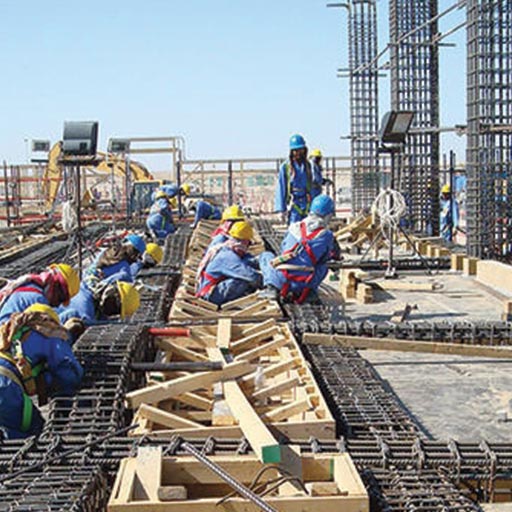
Assessment of an existing structure is a challenging task. The erection of a structure is never exactly as per a designer’s specification and a number of defects and uncertainties crop up during the construction. Moreover, the quality of the materials deteriorated with time and the assessment of an existing structure becomes a time dependent problem. The problem of assessment of an existing structure involves not only the current status of the structure but also its exploration in the life of the structure with or without repairs. There are three sources of deficiency in structures: a) Defect arising from the original design, such as under estimation of loads as per old standards or practices, inadequate section or reinforcement anchorage and detailing; b) Defects arising from original construction, such as under strength of concrete, poor compaction, poor construction joints, improper placing of reinforcement and honeycombing; and c) Deterioration since the completion of the construction due to reinforcement corrosion, alkali-aggregate reaction, etc. A number of techniques have been developed to detect the condition of existing structure (i.e. destructive and non-destructive test).
2. Destructive & Non-Destructive Test
For the different infrastructure project the estimation of mechanical properties can be carried out by several methods such as destructive and non-destructive tests. In destructive testing are carried out to the specimen’s failure, in order to understand a specimen’s performance or material behavior under different loads. Destructive testing explores failure mechanisms to determine the mechanical properties of material such as yield strength, compressive strength, tensile strength, ductility and fracture toughness.
Destructive testing is important because it makes it possible to not only determine possible failure modes but also to evaluate those failures before, after and even while they are occurring. Different types of destructive tests like (core tests, rebar tests, pull out test, geotechnical tests etc) gives the evaluator different kinds of information. Therefore, it is important to be familiar with the various types of destructive tests.
Concrete cores are used for testing of actual properties of concrete in existing structures such as strength, permeability, chemical analysis, carbonation etc. While Rebound Hammer, CAPO/Pullout, Windsor probe and ultrasonic pulse velocity tests give indirect evidence of concrete quality, a more direct assessment on strength can be made by core sampling and testing.
Concrete cores are usually cut by means of a rotary cutting tool with diamond bits. In this manner, a cylindrical specimen is obtained usually with its ends being uneven, parallel and square and sometimes with embedded pieces of reinforcement. The cores are visually described and photographed, giving specific attention to compaction, distribution of aggregates, presence of steel, etc. The core should be soaked in water, capped with molten sulphur to make its ends plane, parallel, at right angle and then tested in compression in a moist condition as per BS 1881: Part 4: 1970 or ASTM C 42-77. The compressive strength of cylinder concrete specimens determined by destructive testing with a compression test machine.
The core samples can also be used for the following:
-
Strength and density determination
-
Depth of carbonation of concrete
-
Chemical analysis
-
Water/gas permeability
-
ASHTO Chloride permeability test
1.1.2 Tensile Testing of Rebar
Reinforcing bars are used in reinforced concrete and are one of the main parts of R.C.C. structure. For that reason, quality of plain and deformed bars should be checked specially for yield, ultimate strength and elongation (ductility). The most important test is the tensile strength test. But sometimes bending test is also done. Tension test provides information on the strength and ductility of materials under uniaxial tensile stresses. This information may be useful in comparisons of materials, alloy development, quality control and design under certain circumstances. Bend test is also a method for evaluating ductility but it cannot be considered as a quantitative means of predicting service performance in bending operations. The severity of the bend test is primarily a function of the angle of bend and inside diameter to which the specimen is bent and of the cross-section of the specimen. Plain round, hot rolled, mild steel bars are commonly used as reinforcement in concrete in Bangladesh. Reinforcing bars with various surface protrusions are also used.
Tensile testing is a very useful and commonly practiced form of destructive testing. During tensile testing, a material is machined to a specific size. The material is made thicker on the ends with a thinner portion in the middle. The two thicker ends are then placed into separate clamps. The ends are thicker than the center so that the failure occurs in the middle rather than near the clamps. Once secured, the specimen is gradually pulled apart at a fixed speed until it fractures.
Stress, strain and elongation data are all captured during this time. Since the material was made to a specific size, the material’s strength can be determined in load/area units. The strain and elongation values are used to determine the material’s modulus of elasticity as well as the yield strength. The amount of elongation that occurs after the yield limit is reached and before final fracture gives the tester a sense of the ductility of the material. For our projects the tensile testing is approved and performed by government authorities (i.e. BUET, CUET). These include ASTM A370, ISO 15630, and ACI 318 standards testing requirement that are specific to determining rebar tensile and bend properties.
Several in-situ tests define the geostratigraphy and obtain direct measurements of soil properties and geotechnical parameters. The common tests include: standard penetration test (SPT), cone penetration test (CPT), flat dilatometer (DMT), pressure-meter test (PMT) and vane shear test (VST). Each test applies different loading schemes to measure the corresponding soil response in an attempt to evaluate material characteristics, such as strength and stiffness.
Boreholes are required for conducting the SPT and normal versions of the PMT and VST. A rotary drilling rig and crew are essential for these test. In the case of the CPT and DMT, no boreholes are needed, thus termed “direct-push” technologies. Specialized versions of the PMT and VST can be conducted without boreholes.
The fundamental principle behind pull out testing is that the test equipment designed to a specific geometry will produce results (pull-out forces) that closely correlate to the compressive strength of concrete. This correlation is achieved by measuring the force required to pull a steel disc or ring, embedded in fresh concrete, against a circular counter pressure placed on the concrete surface concentric with the disc/ring. The pullout test method described in ASTM C900, BS 1881:207, or EN 12504-3
1.2 NON DESTRUCTIVE TEST
Non-destructive testing (NDT) is defined as the course of inspecting, testing, or evaluating materials, components or assemblies without destroying the serviceability of the part or system. The purpose of NDT is to determine the quality and integrity of materials, components or assemblies without affecting the ability to perform their intended functions. Non-destructiveness ought not to be confused with non-invasiveness. Testing methods that do not affect the future usefulness of a part or system are considered to be non-destructive even if they consist of invasive actions.
A number of non-destructive tests are commonly performed for concrete members to determine the field strength and quality of concrete. Some of these tests are very useful in assessing the damage to RCC structures subjected to overloading, aging, corrosion, chemical attack etc. to check a high level of structural safety, durability and performance of the infrastructure in each country, an efficient system for early and regular structural assessment is urgently required in recent years. Innovative NDT methods, which can be used for the assessment of existing structures, have become available for concrete structures, but are still not established for regular inspections. The purpose of establishing standard procedures for non-destructive testing (NDT) of concrete structures is to qualify and quantify the material properties of in-situ concrete without intrusively examining the material properties. There are many techniques that are currently being used for the NDT of materials today are following:
-
Schmidt Hammer Test
-
Ultrasonic Pulse Velocity Test.
-
Rebar Locater Test (Cover meter test)
-
Rebar scan test / Ferro scan
-
Geophysical test (micro tremor)
-
Corrosion Analysis Test
-
Resistivity Meter Test
-
Impact Echo/Pulse Echo Test
-
Ground Penetrating Radar Test
A simple equipment known as Rebound Hammer or Schmidt Hammer is used to determine a surface hardness in order to establish the theoretical relationship between the strength of concrete and the rebound number of the hammer. The details of the equipment are shown in below figure (a, b). Surface hardness measured during the test give an idea about the soundness and quality of cover concrete. Locations having very low rebound numbers indicate weak surface concrete and may be affected by corrosion.
This test was performed on the specimens according to standards (EN 12504-2 2001, EN 12309-3 2003). Schmidt rebound hammer test gave values of rebound number (RN). The compressive strength of the concrete was derived using the chart provided with the device (Aydin and Saribiyik, 2010). A light load was applied on the test pieces to prevent their movement during the test.
1.2.2
The ultrasonic pulse velocity method is used to determine material strength and quality, based on the relation-ship to material density and elasticity. The test equipment has provisions for generating ultrasonic pulse, transmitting it to concrete, receiving and amplifying the pulse and measuring and displaying the pulse travel time. Good acoustic coupling between the transducers and concrete is to be established for correct measurement of the speed (IAEA, 2002). The instrument uses transducers as transmitters and receivers to calculate pulse velocity by measuring transmission time. This flexible unit can measure via direct transmission, semi-direct transmission, indirect or surface transmission to accommodate the demands of virtually any test site. Below figure shows UPV instrument and its observation.
1.2.3
Rebar Detector used to determine the exact location of rebar in existing structure. The Profoscope is a versatile, fully-integrated rebar detector and cover meter with a unique real-time rebar visualization allowing the user to actually see the location of the rebar beneath the concrete surface to a maximum depth of 180 mm (Proceq SA, 2011). This is coupled with rebar-proximity indicators and optical and acoustical locating aids. Rebar diameter can also be estimated within the specified testing range. The Profoscope combines these unique features in a compact, light device that allows to operate this rebar detector with one hand making the task of locating rebars a simple and efficient process. In addition, Proceq’s rebar detector convinces through its intuitive user interface making rebar detection easy.
1.2.4
Ferroscan is portable, non-destructive steel reinforcement detection system using electromagnetic pulse. It can reduce costly effort to drill, cut or physically break concrete surface to find out the bar. Ferroscan used for determining the position, depth and diameter of rebar in existing structure. This is a portable, quick and simple-to-operate system carrying out structural analyses quickly and exactly in a non-destructive manner. This also determines coverage over the entire surface of a structure. The key elements of the system are the scanner and the monitor. After scanning a structure data has been transferred to the monitor. Collected data can be analyzed by monitor or in a PC using PS 200 software’s. Maximum depth of scanning is 185 mm (at 36 mm rebar diameter) where rebar diameter range 6 – 36 mm. Accuracy of depth measurement for rebar is ±1 mm, depending on depth range and scan mode used. Three types of scanning can be checked out by using Ferroscan device. Line scan is simple way to detect position and depth of rebar where Image scan provides detail information (diameter of bar, concrete cover, location etc.) with scanned image (2 ft x 2 ft grid) of any structure. Block scan is a combination of a set of image scan for a comparatively large area (Rahman et. al, 2010). Below figure shows monitor and scanning device produced by Hilti Corporation, 2011.
1.2.5
Any earth and civil structures are continuously subjected to small vibrations, anytime and everywhere, which are not only seismic origin but also random disturbances due to natural effects (winds, sea-waves, volcanic actions, etc.) and human activities (traffic, machinery, etc.). These motions are called microtremor.
Microtremor measurement has become a useful tool for civil engineers in order to estimate ground motion characteristics, amplification of soil deposits (H/V-ratio) [1], microzonation [2], and dynamic behavior of existing structures (cross-spectrum technique and coherence) [3]. At each site, microtremor ground motions were measured for 15 minutes. Each accelerometer recorded data in three direction two horizontal (N-S and E-W components) and one vertical direction (up-down). For free field near to building, First Fourier Transform (FFT) has been done in order to calculate H/V spectral ratio for microtremors. Lower amplitude and higher frequencies are rigid or/and strong, and higher amplitude and lower frequencies are soft or/and vulnerable (see below Figure*). But the actual strength of structures against earthquake ground motion needs more information of structural strength, intensity, frequency and duration of ground motion and soil condition.
1.2.6
Corrosion analyzing instrument highlights corrosion activity before rust becomes visible. Early detection is a key factor in preventing an unanticipated structural failure. Half-cell corrosion potential method -Accurate field potential measurements aid in detecting active corrosion in rebars. The test surface is divided into grids of uniform size.
1.2.7
Concrete resistivity method – the instrument measures the specific electrical resistivity of concrete. Surface resistivity measurement provides extremely useful information about the state of a concrete structure. This is based on the classical four-electrode system in which four equally spaced electrodes are electrically connected to the concrete surface. The two outer electrodes are connected to a source of alternating current. The two inner electrodes are connected to the voltmeter.
1.2.8
For the impact echo / pulse echo test impacting device such as a hammer is struck on the concrete surface. The sound waves that reflect off from voids or discontinuities are picked up by a recovery receiving probe and conveyed to a signal processor. This wave form is analysed in the signal processor, and amplitude and travel time of waves are evaluated for the determination of homogeneity and integrity of concrete.
1.2.9
Ground Penetrating Radar (GPR) is a technique of obtaining sub-surface images using electromagnetic radiation. The energy radiated by the antenna of the system penetrates the surface, and is either absorbed or reflected back at any discontinuities. GPR is valuable for in locating defects and voids in concrete structures, determining embedded reinforcement and other subsurface details. The Structure Scan Standard system provides a nondestructive means to accurately inspect concrete structures. This Structure Scan Standard used to safely locate embedment within concrete structures prior to drilling, cutting or coring. Reach depths of 0-18 inches with confidence using a 1600 MHz antenna, survey cart and SIR–3000 control unit (GSSI, 2011). This is generally used to locate metallic and non-metallic targets in walls, floors. Below figure shows GPR control units and a 1.6 GHz antenna for structure scan.