Site Navigation

Earthing Testing:
To Conduct a proper earthing system bellow process will be applied:
-
The Earth Resistance is calculated using Ohm’s Law: R= V/I.
-
Home / Technical Articles / The most common methods of measuring the resistance of an earth electrode
-
Earth resistance of an earth electrode
-
When an earth electrode system has been designed and installed, it is usually necessary to measure and confirm the earth resistance between the electrode and “true Earth”.
-
The most common methods of measuring the resistance of an earth electrode
-
The most commonly used method of measuring the earth resistance of an earth electrode is the 3-point measuring technique.
-
This method is derived from the 4-point method – which is used for soil resistivity measurements.
-
The 3-point method, called the “fall of potential” method, comprises the Earth Electrode to be measured and two other electrically independent test electrodes, usually labelled P (Potential) and C (Current). These test electrodes can be of lesser “quality” (higher earth resistance) but must be electrically independent of the electrode to be measured.
-
An alternating current (I) is passed through the outer electrode C and the voltage is measured, by means of an inner electrode P, at some intermediary point between them.
-
Our expected result should be below 1ohm for system earthing. And 10 ohm for LPS Earthing system.
Insulation Testing:
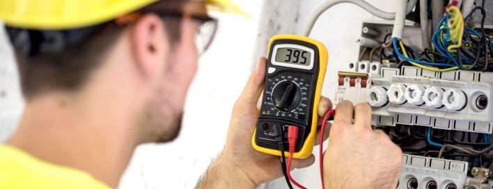
Insulation resistance measurement is done using an IR tester. This is a portable tool that is more or less an ohmmeter with a built in generator that’s used to produce a high DC voltage. The voltage usually measures at least 500V, and causes a current to flow around the surface of the insulation. This gives a reading of the IR in ohms.
Insulation resistance measurement is based on Ohm’s Law. (R=V/I). By injecting a known DC voltage lower than the voltage for dielectric testing and then measuring the current flowing, it is very simple to determine the value of the resistance. In principle, the value of the insulation resistance is very high but not infinite, so by measuring the low current flowing, the megohmmeter indicates the insulation resistance value, providing a result in kW, MW, GW and also TW (on some models). This resistance characterizes the quality of the insulation between two conductors and gives a good indication of the risks of leakage currents flowing.
Well, if you are looking at a high number of IR, you have some good insulation. If it is relatively low, on the other hand, the insulation is poor.
However, this is not everything – a variety of factors can affect the IR, including temperature and humidity. You will have to do a number of tests over time to make sure the IR value stays more or less the same. Value of insulation resistance is often expressed in gigaohms [GΩ].
Good Insulation is when megger reading increases first then remain constant. Bad Insulation is when megger reading increases first and then decreases.
THE expected IR value gets on Temp. 20 to 30 degree centigrade. If this temperature reduces by 10 degree centigrade, IR values will increased by two times. If the above temperature increased by 70 degrees centigrade IR values decrease by 700 times.
In order to measure big electrical resistance, measurement voltage has to be far higher than it is in case of standard resistance measurements. This voltage is often within the range from 100 VDC to 1000 VDC and it cannot be used for measuring resistance of electronic components because they could be damaged.
Minimum Resistance should not be less than 5 Mohm according to BNBC.
Thermographic Scanning:
Unwanted heat generation is very bad for the electrical system. If any electrical system produces unwanted heat then it is obvious that there is an electrical fault. So regular thermographic scanning is necessary for system. Thermographic scanner is used to scan the system.


